|
| |
|
The Assembly (click
on pictures for large image)
|
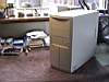 |
The first thing we need to do is open the
case and prepare the base plane to receive the motherboard.
Each case is build differently, but in our case I removed the plastic
front plate by prying it off with my hands.
I then removed three screws on the back of the case
allowing me to slide off both side covers and finally removing the top
cover. Now the interior skeleton of the case is exposed.
*Note: The base plane is the plate
inside the computer the motherboard is connected or screwed into,
typically a large flat section the motherboard sets upon.
|
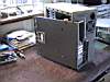 |
Now it is just a matter of
releasing the base plane from the case and sliding it out off the case.
Removing the base plane allows for easier attachment of
the motherboard. If it is possible with your case, you should follow
this step. Not all cases allow you to remove the base plane,
(especially the very inexpensive cases). In using these cases you
will be forced to seat the motherboard into the case. This is more
awkward.
|
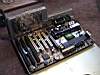 |
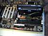
Taking the motherboard and laying it on top
of the case's base plane, I can see where I will need to have stand offs,
(small metal studs or plastic nylon studs), to attach the motherboard to
the base plane. I placed two metal studs on the base plane, (one on
either side of the motherboard), and the rest of the holes have
corresponding nylon studs. This provides for full support of the
board and keeps the solder joints from touching any part of the case.
I do not use the fabric washers that come with the case.
I like a clean contact between the motherboard and case for electrical
grounding. If you have attached the motherboard properly, it align
with the openings in the back plane of the case for your component cards
and ports.
*note: The back plane is the area of
the case to the rear of the computer that the video card, modem or other
cards are screwed to and open out for access to the features of the cards.
Sometimes this is referred to as the rear slot area of the case.
|
|
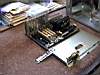
The next step is very
important. Normally at this time I would set the jumpers on
the motherboard for the speed of the CPU, (PII-350), I would be adding.
Always double check that these settings are correct. In the case of
this computer, Microstar uses CMOS settings, or Bios software to configure
the CPU. This saved me from digging through the manual for the
settings and then pulling jumpers with my needle nose pliers. This
is a nice feature.
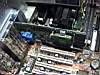
Then I take the CPU, locate the 'Slot One' slot on the
board, (the slot will only accept the CPU and is nearly always turned 90s
to the direction of the other board slots) and then slide the CPU into
place, pressing down gently to snug it into the motherboard.
You will notice that the CPU and 'Slot One' have three separated sections
and the CPU will only go into the slot one direction. This is the
first example of using common sense and not forcing the component.
With the CPU in place, I take the small electrical wire
accompanying the CPU and connect it from the CPU to the motherboard.
It only attaches one direction on the CPU and the motherboard has a
clearly defined set of pins marked: CPU FAN. It connects easily.
The CPU comes with small additional braces to support
the weight of the heatsink and fan. I never use these for home
systems. A home computer does not have the motion abuse to require
these additional braces.
I then take the 64mg SDRam module and press it into the
1st ram slot. (If you are unaware which one is considered #0 or the
1st slot, consult your motherboard manual). When the
module is pressed into place the locks on each end of the ram module will
snap into place. You cannot seat a SDRam module backward, as the
base only fits in one direction. We are now ready to reattach the
base plane to the case.
|
 |
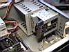
I now reattached the base plane of the case
with the motherboard attached to the case. Some cases require
screws to hold it in place, but the Enlight case has a release handle that
is pressed to hold it securely.
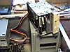
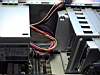
The next step is to connect power to the motherboard.
PentiumII motherboards are ATX by design and use a special power
connector. If you examine this connector, (the largest one coming
from the power supply) and the motherboard's power connector, you will see
it can only be plugged into the motherboard one way. DO NOT
FORCE IT... it should plug in easily.
|
|
The next step is the video
card. I am going to connect the video card next to facilitate
a quick test of my work so far.
The video card I am using is an AGP card. The AGP
slot is the nearest slot next to the CPU on the motherboard. You
simply remove any covers on the backplane for the slot and then press the
video card into the AGP slot. Then use a mounting screw to attach
the card to the back plane. We are now ready to test the system.
I attached a power cord to the power supply, attached a
basic PS/2 keyboard to the keyboard port on the outside of the back plane
and then ran the video cable from the monitor to the video port on the
back of the video card. Then, it was a simple matter of pressing the
power switch on the front of the case. The computer flared to life,
displaying the post or boot process on the screen.
If all has gone well, as in my case, the monitor will
display the post process and allow you access to the CMOS settings using
the keyboard.
|
 |
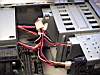
It is time to connect the case wires to the
motherboard. These are the small wires running to the power
switch, the reset switch, hard drive led light, power led light on the
front of the case.
It is best to use your motherboard manual to determine
the exact pins on the motherboard. The wires in this case are each
clearly marked for each connector. In the case of this case the
white wires are the negative wires, (this is not always the case).
If you connect a wire the wrong direction, nothing will happen except the
light will not come on. Just remove the wire and turn it around.
|
|
Now to the Floppy drive,
hard drive and CD Rom drive. I am going to attach the hard drive as
a single drive on the 1st IDE channel and the CD Rom drive as a single
drive on the 2nd IDE channel. I then verify that the hard drive has
the jumpers set to be a single drive and I set the jumpers on the CD Rom
as a master drive also. I recommend doing this before you
attach the drives so you can more easily move and jumper pin covers.
The next step is to attach the drives. I removed
the 3.5inch drive bracket from the case by pressing the spring locks
holding it in place and sliding it out. Then I screwed the floppy
drive and the hard drive into the bracket, so that the floppy drive would
align with the plastic face plate and the hard drive would remain within
the case.
Now it was a simple matter of sliding the mounting
bracket back into the case until the spring locks snapped into place.
These two drives are now seated tightly.
|
|
Now for the CD Rom drive. In this case
it is only a matter of attaching the side rails that accompany the case to
the drive. This is done with two screws on each side of the drive.
One tip about CD Roms and screws: there are two rows of screw
holes on the sides of a CD Rom drive. If the tray is on the top of
the drive, put the screws into the bottom set of holes and vice-versa.
You do not want the screws to damage the inner workings of the CD tray.
Now it is just a matter of sliding the drive into the
appropriate opening in the case, as the rails will snap into place with
the spring locks when slid into place.
One more note: most cases do not have nice slide
rails to mount drives. Usually you will need to slide the
drive into the opening and then screw it into the case. The is a
nice advantage of the Enlight case.
|
|
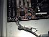
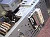
It is time to attach the
power wires to the drives. This is really straight forward.
The remaining wires from the power supply have connectors that will only
attach to the appropriate power connectors on each drive. I attached
a power wire to the hard drive, the floppy drive and the CD Rom drive.
I like a neat appearance inside, so I also used some small wire ties to
bundle the wires together.
The next step is the ribbon cables to the drives.
First I attached the floppy drive ribbon cable. I did this by
determining the pin#1 on the motherboard and the floppy drive. Then
I attached the floppy drive ribbon cable to the motherboard with the red,
(or any color), stripe toward pin#1 on the floppy connector and the same
on the drive. The connector on the ribbon cable that must be
connected to the floppy drive has a 'twist' in the cable directly next to
the connector. This designates this drive as the "boot"
floppy. This is important.
I then took the IDE ribbon cable and connected it to the
IDE-1 connector on the motherboard with the red stripe toward pin#1 and
ran the cable to the connector on the hard drive with the red stripe once
again toward pin#1. I then ran a second ribbon cable from the IDE-2
connector on the motherboard to the CD Rom drive following the same
procedure.
*Note: Determing the pin#1 on the
motherboard can be tricky. Often you will see a number one,
(1), to one side of the connector. Sometimes it is easier to review
your motherboard manual, (usually there is a drawing of the motherboard
displaying which side is pin#1).
Determining pin#1 on drives is far
easier. It is nearly always the pin adjacent to the power connector.
If a drive is not recognized by the system, try reversing the ribbon
cable... it maybe connected backward.
|
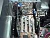 |
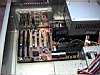
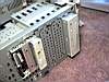
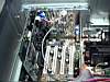
The next step is to add in the remaining
component cards. First I took the Sound Blaster AWE64 card and
pressed it into the first ISA slot. This slot is the one
adjacent to the PCI slots and if this confuses you, I recommend consulting
your motherboard manual's diagram of slot configuration.
Typically the ISA slots are the last set, farthest from the CPU.
Since this is a plug-n-play card there are no jumpers to configure.
I then attached the card to the back plane with a mounting screw. |
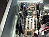 |
Now for the final card, the
modem. Once again this is also a plug-n-play card and I just
pressed it into the next available ISA slot, then attached it to the back
plane with a mounting screw. |
 |
My final item to attach is the CD Rom sound
cable. This small cable came with the CD Rom drive. It
attaches to the four prong slot for it on the back of the CD Rom drive and
extends to the sound card. The sound card has a small connector that
this cable connects into. This cable is important is you wish to
play audio CDs in your computer, if not... you can omit it. |
Now for one final test, I inserted a
Win98 boot disk into the floppy drive and booted the system.
During the post phase, I pressed the 'DEL' key and entered the CMOS
settings. In here I had the system auto detect the hard drive for
the parameters. I save the settings and rebooted. The system
fired up the first time, nice and clean.
Now it is only a matter of attaching the
side & top plates to the case and then pressing the front plastic
cover back on. I am now ready to partition my hard drive and
format. Since I am going to load Windows98 and this is an 8.4gig
hard drive I made one fat32 8.4gig partition and then formatted the
drive.
Building a computer is really just this
simple. It is no mystery or secret. The only thing
left to do is actually load Windows98 and the other software the belongs
on the system.
|
|

)
)
)
)
)
)
)
)
)
)
)
)
)
)
)
)
)
 E-Mail: